VITESS Universal Module Bender

The module Bender is similar to the module Guide using the bender option. The main difference is that the 'bended guide' consists of several straight parts that form a polygon section. In contrast, the bender surfaces are circles (but straight surfaces also possible). Also the module Bender simulates converging (diverging) bender-polarizator with possibility of enabled or disabled of polarising neutrons. The 2-D visualization of surfaces and trace of neutrons path are included (using PGPLOT and G2 graphic libraries). Only first 10000 trajectories will be visualised. Also you can choose the device for visualisation: display, file or both.
Additionally there is a possibility to have spacing inside the bender.
THE SURFACES IS SITUATED IN XZ PLANE.


  Picture 1. One channel of the bender
 

Simulation parameters

The effect of gravity is considered in this module, if this option is chosen. Neutrons with a probability/current less than the 'minimal weight' are taken out of the simulation. The possibility take into account the rough of reflected surface of guide is included also. Abutment loss feature is rejecting neutrons, which have got reflection near edges (exit) of bender. If last path of neutron (before exit plane) is smaller than given value, such neutron is rejected. User also must to input this value. The polarizing of neutrons may be enabled or disabled. For each spin direction (-1 or 1) user must be input individual reflectivity file for left, right planes of bender (This is not actually for top and bottom planes, but it is possible too). If polarization is included, neutrons, which has another quantization is rejected.
 

Bender Geometry characteristics

The geometry of bender is defining by following parameters:
1. Entrance height (along vertical axis 0Z).
2. Exit height (along vertical axis 0Z).
3. Length of the bender.
4. Radius of curvature; Angle beta=(Length of bender)/(Radius of curvature) is defining angle of decline of exit sufrace concerning entrance surface of the bender so the bender axis is part of circle. If radius of curvature is zero, the central axis of bender is a straight line and so angle beta is zero. The parameters which are describing arrangement of vertical surfaces in the horizontal plane (XY - plane) are reading from the parameter file, which have name - surface file.

Please NOTE! Subsequent modules always refer to the new origin, which is defined as the middle of the exit window. It is generated automatically by the program, also in the case of curvature (the orientation of the frame follows the curvature).
 

Reflectivity Files

The reflectivity files describe the reflection properties of the coating:
mirr0.dat:  absorbing coating  (reflectivity = 0.0)
mirr1a.dat: theta_Ni coating   (theta_Ni = 0.099138 deg)
mirr1b.dat: theta_Ni_58 coating (theta_Ni_58 = 0.11456 deg)
mirr2.dat: super-mirror coating (2 theta_Ni)
mirr2linear.dat: supermirror coating,
  reflecitivity 0.99 -> 0.9 from theta_Ni to 2 theta_Ni; cutoff at 2 theta_Ni;
mirr3+.dat: super-mirror coating (3.5 theta_Ni)
The reflectivity file contains the probability of reflection in dependence of the incident angle for neutrons with a wavelength of 1 Å. Each row contains 10 data points and covers 0.01 deg, i.e. each point gives the probability average over an angular interval of 0.001 deg (the second row covers 0.01-0.02 deg a.s.o.). The number of data points may vary between 1 and 1000. If end of file is reached (e.g. only 52 values are given) the probability to reflect 1 Å neutrons for higher angles is set to 0. If no reflectivity file is given as an input or mirr0.dat file is given, the guide operates in total absorption mode, i.e. each neutron is hitting a guide wall is lost or transmited in the next channel (depending from mode).
There are files for the left (= inner) side, for the right (= outer side) and for the top and bottom of the bender (channels); in each case there is one for spin-up and one for spin-down neutrons. This is necessary for simulation of polarizing devices.
 

Surface File

The entrance and exit position of each surface and its radius have to be given in a file, called surface file. All benders that can be described in that way can be simulated. Surface file must be written by user and to input with option -u. The format of parameter file, which describing surfaces is:

Displacement in the entrance surface (cm), Displacement in the exit surface(cm), Raduis of curvature (cm) ...Another surfaces.............................................
Example (11 surfaces, converging bender):
-10.0 -5.0 2000.0
-8.0 -4.0 2000.0
-6.0 -3.0 2000.0
-4.0 -2.0 2000.0
-2.0 -1.0 2000.0
0.0 0.0 2000.0
2.0 1.0 2000.0
4.0 2.0 2000.0
6.0 3.0 2000.0
8.0 4.0 2000.0
10.0 5.0 2000.0
Please NOTE! For positive value of radius of curvature the circle will be concave. If radius of curvature of sufrace is zero, the straigth line will be used instead arc line. This is useful for simualtions of some soller collimators. If negative value of radius of curvature is given, the circle will be convex. Such features are giving the possibility for simulating of many types of benders and collimators!
The number of surfaces must be less than 200. The module defines the number of lines in the parameter files automaticly. Number of lines equally numbers of surfaces in multiple collimator. Please do not to writing incorrect data in the parameter file (For example, description of hole without radius, Line: -10 -5.0 empty). The entrance and exit width of bender is defining automaticly. Also user must be chosen the thickness of surfaces.

Information file

This file generates after run of simulations and contains some useful information about geometry of the bender.

Visualisation

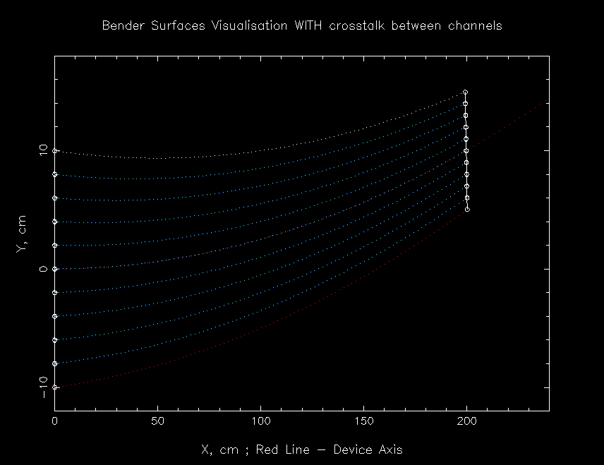
The visualization of the bender, which desciribing above-mentioned file is given at the picture 2. (Length 2m, Radius of curvature 20m, thickness of surfaces is neglecting). During simualtions, the neutron flight paths will be appeared. After first reflection, the color of neutron path is changing, so this is giving the possibility for exploring background of fast neutrons and "straight line" gamma-rays.
For UNIX operation systems (Linux, SunOS, Solaris, OSF1,..) the PGPLOT graphic library is used
For Windows operation system the PGPLOT and G2 graphics libraries are used.


Picture 2. Visualisation of bender channels, view from above

Module parameters:


Parameter Unit

Description

Command option

entrance height
[cm]
size of the guide entrance (in z-direction) -h
exit height
[cm]
size of the guide exit (in z-direction) -H
substrate width
[cm]
thickness of the material that separates two neighbouring channels,
usually the small part of the neutrons is passing in the next channel via that
material
-s
length
[cm]
length of the bender -l
spin up:
left, right, top/bottom plane
reflectivity file for the coating of the guide on the inner side (left), on the
outer side (right) and on the top and bottom plane for spin up neutrons
-i, -m, -k
spin down:
left, right, top/bottom plane
reflectivity file for the coating of the guide on the inner side (left), on the
outerside (right) and on the top and bottom plane for spin down neutrons
-I, -M, -K
surface file file which is containing the entrance and exit positions of the channel borders and
their radii
-u
surface waviness
[deg]
waviness of the inner guide surface, i.e. deviations from a perfectly
plane surface
-r
abutment loss length neutrons that hit the surface close to one of the ends of the guide (<= length) is rejected. -a
visualisation yes: graphics of the neutron paths will be stored on the given device during the simulation
no : no graphics stored
-y
device Choose the device for graphic visualisation: 1-display, 2-file, 3-both -o
polarisation yes: splitting into spin-up and spin-down and using different reflectivity files depending on the spin state
no : no polarisation considered, spin-up reflectivity files used for all neutrons
-p
unreflected neutrons Value 0(No) : neutrons that are not reflected are absorbed .
Value 1(Yes): neutrons that are not reflected are transmitted with attenuation
according absorption material (see options -z and -w), neutrons
which transmitted via extreme surfaces (left and right) are absorbed.
-g
test of bender geometry if activated (value 1) the test of bender geometry is carried, else is not carried. This is useful for bender
with non-standart geometry. If you have received a warning message, please contact with the author of module: manochine@hmi.de
-t
number of axis for spin quantization this feature using with polarising neutrons. if spin of neutron is parallel (antiparallel) of axis
0X or 0Y or 0Z, this value must be 0 or 1 or 2 accordingly. The default value is 0 (axis 0X),
so the magnetic field is parallel of axis OX.
-V
information file name of file, which contain some information about geometry of bender -A
radius of curvature Radius of curvature of base circle-axis of bender
(if zero - bender axis is straight line)
-R
absorption material in the channel the absorption coefficient of the material inside of the bender channel
Active, if neutrons are transmitting between channels of bender: Option -g1
-c
transmission file of bender channel File, which characterized the transmission of
material inside bender channel.
Active, if options -g is unit => -g1 and -c is zero => -c0.
-C
first absorption material Absorption material in the inner(left) side of the channel
See from bender entrance - left side.
Active, if neutrons are transmit between channels: Option -g1
-z
transmission file of left side of channel File, which characterized the transmission of
material in the left side of channel, see from entrance.
Active, if options -g is unit => -g1 and -z is zero => -z0.
-T
second absorption material Absorbpion material in the outer(right) side of the channel
See from bender entrance - right side.
Active, if neutrons are transmit between channels: Option -g1
-w
transmission file of right side of channel File, which characterized the transmission of
material in the right side of channel, see from entrance.
Active, if options -g is unit => -g1 and -w is zero => -w0.
-O


List of absorption materials, which were included in the module (for the options -c, -z and -w):
Value 0 - Read data from file, which was created by user
Value 1 - Gd: Gadolinium.
Value 2 - Cd: Cadmium.
Value 3 - B: Bor10.
Value 4 - Eu
Value 5 - Si: Silicon.
Value 6 - Vaccum, no attenuation
For values 1-4 wavelength range must be between 0.3 ... 28 A in the source module or virtual source.
Foe value 5 wavelength range must be between 1 .. 20 A in the source module or virtual source too.
This datas were given by Thomas Krist, HMI, Berlin.

The format of file, which description the transmission is:
Wavelength, A Value MU, cm^(-1)
................ .......................

The wavelength values in the table must be increased!
The number of rows must be less that 500!
Then, the transmission is calculated by formula: "Transmission" = exp(-MU*Distance);
where Distance is length of flight of neutron in given material in cm, which calculated automaticly. During passing the neutrons via material, the "Transmission" value is multipling in neutron probability.
The wavelength range must be from smallest to longest wavelength in the table. If you have used material from list and material from file, please choose the minimal and maximum wavelength values in the source module (or virtual source), which do not extend the wavelength range of transmission materials for left and right sides and for bender channel material. Otherwise, the simulation process will be cancelled automaticly.


Back to VITESS overview
vitess@hmi.de, manochine@hmi.de, lieutenant@hmi.de

Last modified: 30.09.2003  Tuesday, 03-Jul-2007 16:14:08 CEST